System/1 Build Log
An ongoing chronology of System/1's construction, and any other related musings.
20th June, 2015 - Things are taking shape!
It's been a while since my last update, although I've not been entirely idle; over the past few weeks I've put together the final design for System/1's control unit, which is going to be a hardwired piece of hairiness (microcode is boring!)
In the end it turned out the biggest challenge was arranging the schematics so they're vaguely readable; it became obvious quite quickly that it wouldn't all fit on the standard A3 sheet I'm using (EAGLE seems to have some massive logic gate symbols, but I have a handy A3 pen plotter so I might as well use it). The first draft was spread across two sheets; then I started fiddling around...
The first change to my original design notes was the shift instruction — I realised that the original design was a bit dodgy, in that shifts in one direction had their magnitude bits encoded as the 32s-complement of shifts in the other direction (because the shifter is going to be implemented as a circular shift register with taps and masks), and also required that the shift magnitude was encoded in the immediate field. Some late-night beard-scratching a while ago suggested a better design for the shifter that allowed the magnitude to not only be represented naturally for shifts in both directions, but also to be specified from the second source register as well as just the immediate field. Who knows, that might be handy one day!
Once that change was made, it also struck me that the same 'second source register or immediate field?' logic would apply directly to the word-concatenation instruction — thus giving me the 'load immediate high word' instruction mentioned in the notes on the word concatenator itself. For the grand total cost of one additional OR gate, this seemed like a good deal.
These changes, of course, were made in the middle of several iterations of going over the schematics with a highlighter and a table of output signals, making sure everything looked good on paper — a couple of mistakes jumped out during this process, so the hours definitely weren't wasted (I'd have looked pretty silly if I'd forgotten to put the data on the bus for memory stores!). At some stage it occurred to me that relative jumps/calls should probably take a signed immediate operand, but absolute jumps/calls should treat theirs as unsigned... and at about that point I decided to split the schematic across three sheets, and suddenly it all looked rather more manageable.
That, then, brings us up to last weekend, when I sat down with the breadboard and an awful lot of jumper wires and put this monstrosity together:
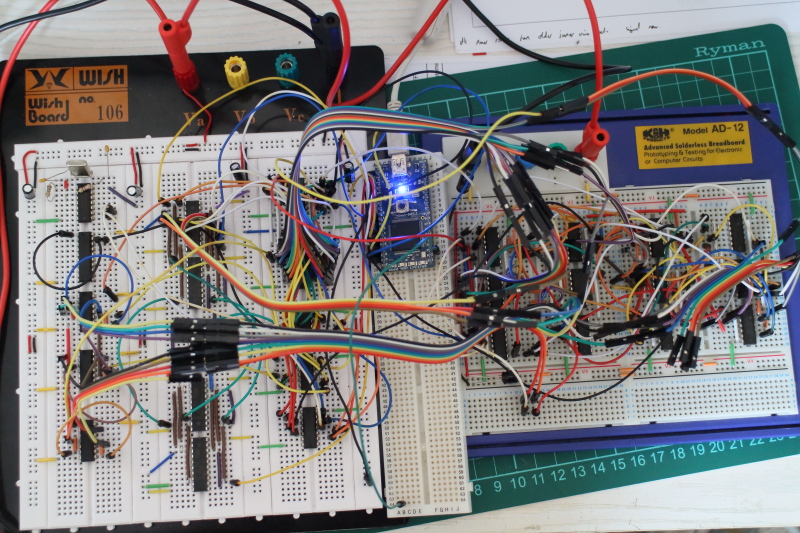 Somewhere under that pile of wiring lurk the 27 chips implementing the brains of System/1...
A few evenings this week have been spent writing a test harness for it on the mbed, which is hiding on the narrow breadboard in the middle of that picture. The test code simulates both the clock generator board (because I'm not going to build that until I'm sure my timings are sensible) and the memory interface (so it can force-feed the instruction word with a prearranged stream of instructions); by running through a complete execution cycle for each of the 256 opcode/subop combinations in turn and recording the results seen on a flying-lead probe, it builds up a truth table of output signals:
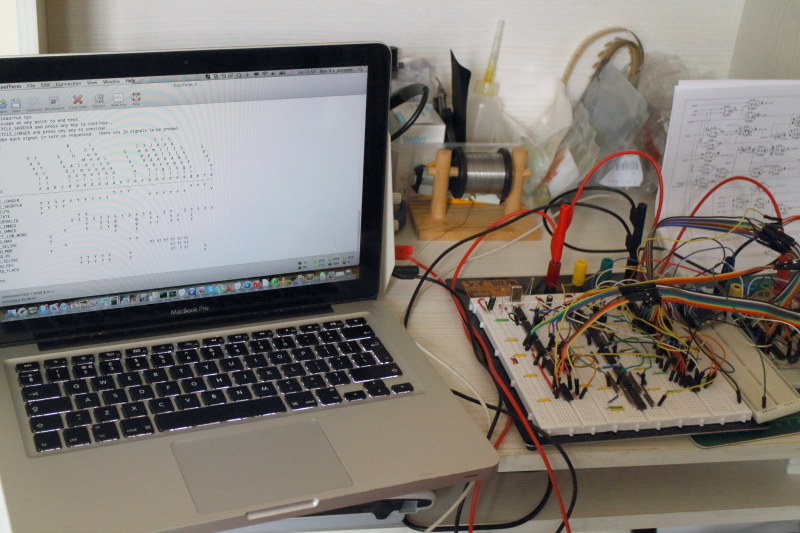 ... and after a little debugging of misplaced wiring, they even look like they're right.
So far, so good; once I'd corrected the odd wiring mishap where I'd hooked a signal up to one pin and scribbled a completely different one down on my working copy of the schematic, the output signals all line up with expectations. The next step will be to wire this lot up to the backplane and see how well it can compute when it has an ALU and some registers to talk to.
One thing that did crop up during this testing, though, was a curious set of '?' flags on some results; this flag indicates that the probed signal depends on the state of the CONDITION_MET backplane signal, and should have been confined to the LOAD_PC and LOAD_REG lines during the execution of conditional jumps and calls. However, it was showing up for some arithmetic instructions too, which should never be conditional; worse, it wasn't doing so consistently! The issue turned out to be pretty simple (and obvious); the mbed was reading its input line immediately after changing the state of the CONDITION_MET line, and the signals that were showing up as confused were at the end of the longest chains of gates. Now, I'm not certain at the moment just how short a window the mbed leaves between the set and the read; I guess that means it's time to break out my favourite toy, the logic analyser, and see about measuring the end-to-end delay. Which, after all, is what I said I was going to investigate last time...